Custom Designs
Frequency-specific design for size, gain, bandwidth, and polarization targets.
Antenas: Monopole, Dipole, Yagi-Uda, Helical, Microstrip
Phase Shifters: Reflection Type, Switched Line, Loaded Line
Austral Microwaves builds compact microwave rf designs for custom integration, lab evaluation, and engineering prototype work. Our works include circular and linealy polarized patch antennas, phase shifters and phased-array development hardware.
Frequency-specific design for size, gain, bandwidth, and polarization targets.
Antenas: Monopole, Dipole, Yagi-Uda, Helical, Microstrip
Phase Shifters: Reflection Type, Switched Line, Loaded Line
S21, S11, radiation pattern, gain, and axial-ratio report-ready plots for engineering review.
Development support for array architecture, feed concepts, and beamforming demos.
Our Team

Electronic Engineering Consultant
Creator
Antenna, Phase shifters, Phased arrays design & characterization Consulting.
Software Defined Radio Consulting.
ANSYS HFSS, CST Studio, Keysight ADS
SPICE, Verilog, VHDL
Designs
Category
Compact circularly polarized reference hardware for TT&C, CubeSat, and lab work.
Circularly polarized S-band antenna for telemetry, CubeSat, and integration work.
High-value development hardware for beamforming demos, research, and control experiments.
Category
A continuously tunable phase-shifter design based on a varactor-loaded reflection topology.
A digitally controlled PIN-diode design for repeatable, discrete phase selection in S-band systems.
Available as prototype hardware, technical documentation, and starting points for custom RF programs.
Featured Antenna
Circularly polarized X-band reference hardware for engineering evaluation, bench characterization, and integration studies around the 8.425 GHz target.
A characterized X-band circularly polarized patch intended as engineering reference hardware for CubeSat, TT&C, and microwave integration work, with simulation, measurement, and prototype fabrication data aligned around the 8.425 GHz band.
| Parameter | Simulation | Measurement |
|---|---|---|
| Center frequency | 8.425 GHz | 8.4 GHz |
| S11 | -22 dB | -12 dB |
| Matching bandwidth (S11 < -10 dB BW) |
920 MHz | 800 ± 30 MHz |
| Broadside gain | 7.06 dBi | 6.5 dBi |
| Parameter | Simulated value |
|---|---|
| Operating frequency | 8.425 GHz |
| Reflection coefficient at 8.425 GHz | -22.14 dB |
| -10 dB impedance bandwidth | 927.3 MHz |
| Minimum axial ratio at broadside | 0.55 dB |
| Frequency of minimum axial ratio | 8.43 GHz |
| 3 dB axial ratio bandwidth | 218.7 MHz |
| Broadside gain | 7.06 dB |
| Back-lobe attenuation | -12.32 dB |
| RHCP polarization ratio at broadside | 35.75 dB |
S-band Antenna
Circularly polarized reference antenna for S-band telemetry, CubeSat, and microwave integration work.
Single-element RHCP patch hardware with simulated impedance, axial-ratio, and radiation-pattern characterization around the 2.245 GHz operating band.
| Parameter | Simulated value |
|---|---|
| Operating frequency | 2.245 GHz |
| S11 near target | ≈ -36 dB |
| -10 dB impedance bandwidth | 59.9 MHz |
| Minimum axial ratio | 1.10 dB |
| 3 dB axial-ratio bandwidth | 15.4 MHz |
| Broadside gain | 6.92 dBi |
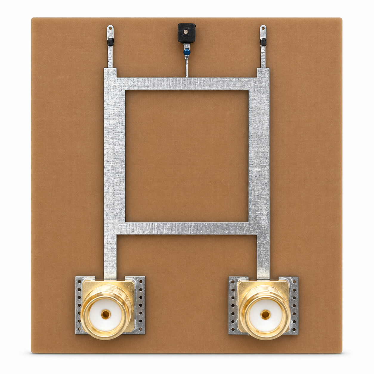
Featured Phase Shifter
Wideband RTPS prototype hardware with voltage-controlled phase adjustment, characterized across a 300 MHz span in S-band.
This reflection-type phase shifter uses varactor tuning to provide continuous phase control from 2.0 to 2.3 GHz. Measurements across the bias range show approximately 100° of available phase adjustment throughout the characterized frequency span.
Featured Phase Shifter
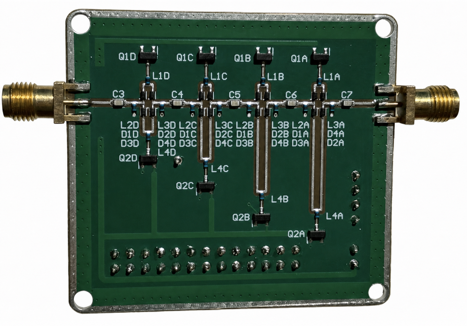
A four-bit RF prototype that selects discrete phase states through PIN-diode-switched transmission-line paths, with embedded I2C control for system integration.
The board combines four switched-line stages in a compact two-port format. Each stage uses series PIN-diode switching to select its RF path, enabling repeatable digital phase control from a host processor or embedded controller.
Featured Array
Bias-controlled S-band array hardware for beamforming development, matching studies, and measured-versus-simulated radiation analysis around 2.15 GHz.
A 2x2 patch array reference design built for CubeSat phased-array prototyping, steering validation, and RF characterization. The supporting material covers front and rear hardware views, S11 behavior across phase states, bias-current sensitivity, and measured/simulated lobe comparisons.
| Parameter | Measurement |
|---|---|
| Operating frequency | 2.15 GHz |
| Bandwidth | 20 MHz |
| S11 | -16.56 dB |
| Broadside Gain | 7.83 dBi |
| Phase resolution | 5° |
| HPBW | [28°-38°] |
| Scan range | ±40° |
Contact
Share the target frequency, bandwidth, polarization, size limits, and integration constraints to scope prototype hardware or custom design work.
Email a Design Request